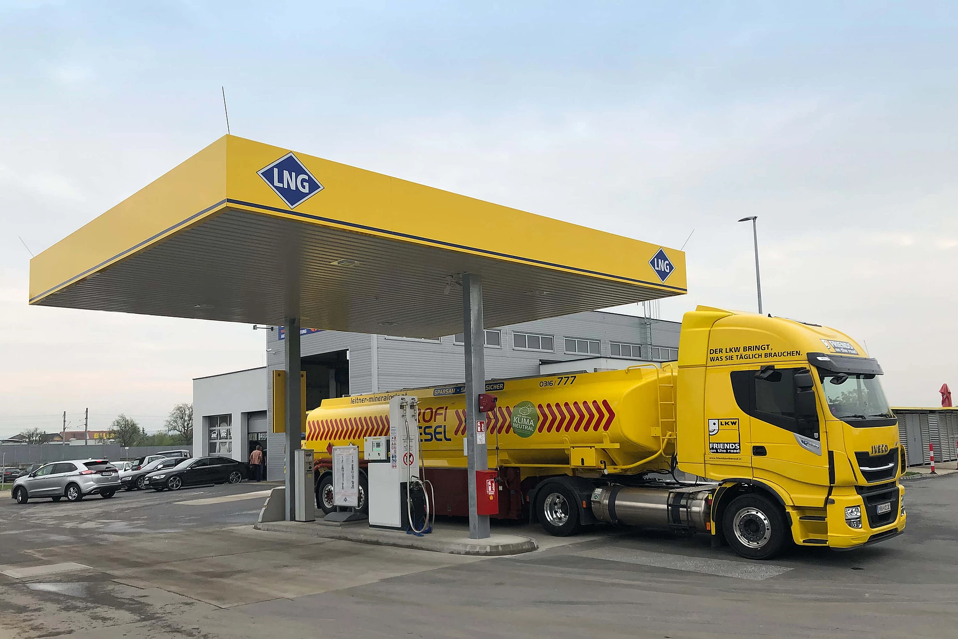
In 2019, RAG and its business partner F. Leitner Mineralöle GmbH built an LNG filling station in Graz.
Operation is carried out by F. Leitner Mineralöle GmbH. Refuelling with LNG is possible daily throughout (0-24 h).
Due to regulatory requirements, the use of the LNG filling station is only possible after prior training of the drivers.
Simple steps to use the LNG filling station:
- More information about the filling station:
- Drivers training
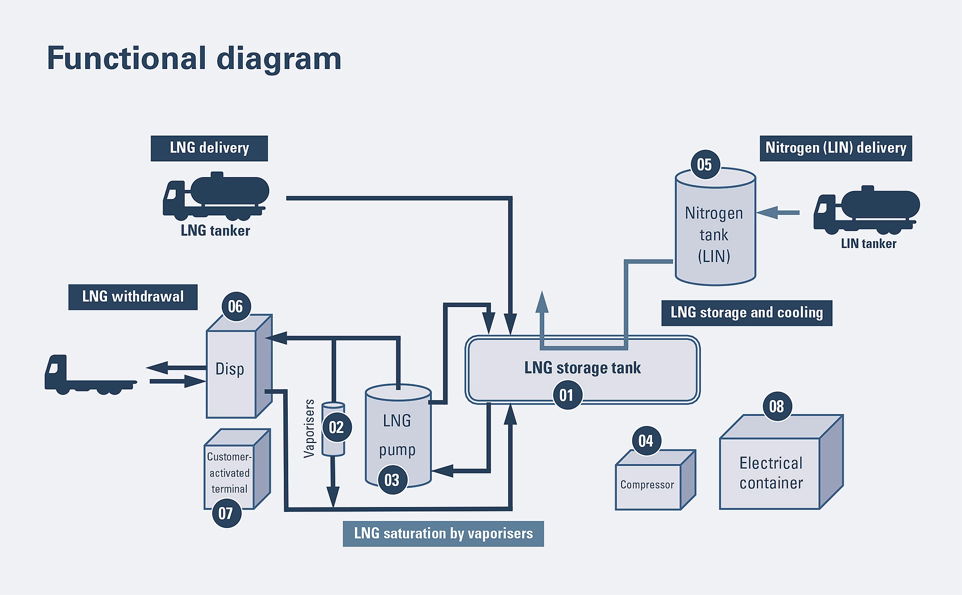
Functional diagram
01 | LNG storage tank
The LNG storage tank is a horizontal, cylindrical, doublewalled container, which is vacuum-insulated using perlite. The inner container is made from stainless steel, and the outer container from carbon steel.
02 | Vaporisers (pressure build-up and saturation vaporisers)
Pipes with star-shaped aluminium fins are attached along either side of the container, to act as vaporisers. These provide pressure build-up when the storage tank is filled and saturation when LNG is withdrawn via the dispenser.
03 | LNG pump
The built-in immersion pump is permanently submerged in the LNG.
04 | Air compressor (piping)
The air compressor and drier are built in to an ISO standard frame with the required process valves and piped connections.
05 | Nitrogen tank (LIN)
When necessary, liquid nitrogen is used to cool stored LNG; it is stored in a separate tank.
06 | Dispensing pump (dispenser)
LNG is withdrawn via the dispensing pump. Withdrawal volume is measured using an integrated mass flow meter.
07 | Customer-activated terminal
The customer-activated terminal opens the dispenser, allowing truck drivers to refuel using a special card.
08 | Electrical container
Electrical switchgear and the control system are built into a separate container.
LNG Filling Station Graz
Anton-Hermann-Straße 3
8073 Feldkirchen bei Graz


